Tuesday 29 December 2015

Our TundraTrike RC Plane!

Hi again everybody! It hasn't been very long, and I know that I wrote only yesterday, but I recently put a new battery in my camera, and decided that I should write about some more personal things, as oppose to just information. So I took some photos of the foam board RC plane that my Dad and I built a couple of years ago. Here's what the plane looks like:

The underside of the plane 
A view of the plane from a back view as it was hanging on the ceiling

We decided to call it The TundraTrike because of the utility/bush plane type appearance from the
two-and-a-quarter inch front wheel and the two-and-a-half inch back wheels. This size of wheels works fairly well on a 580 gram plane on the average grass but we recommend three-inch wheels instead because the takeoffs were sometimes very . . . sketchy. Also more clearance between the prop and the ground. When my Dad designed it, he gave the wing a low aspect ratio of five so that the wing could carry all of the plane's bulkiness along with making it a reasonably maneuverable trainer RC plane.  It has an E-flite Park 370 motor with a 7-inch pitch propeller that (I think) has a diameter of 8 inches which gives means that the plane can fly at about sixty km/h and it has a thrust-to-weight ratio of almost one, because it comes close to hovering vertically for a few seconds when its in a vertical position. Even though I had already been flying in the simulator for a few years, it is always good to start with a very easy-to-fly RC plane when you begin flying in real life because it is a very different experience.

I will try to find some videos of this plane flying that blogger will accept because the ones that I have tried to upload so far have had to much content for blogger.

Monday 28 December 2015

Receiver, ESC, Motor, Battery and Propeller

Hello everyone! In terms of power systems, there are five essential ones in RC planes. As you saw in the title, they are the receiver, ESC or engine speed control, motor, battery and propeller. Let's talk about them all.


Receiver

I like to think of the receiver as the central piece of electronics on an RC plane. The engine speed control or ESC and all of the servos connect to the receiver. When you make a certain control input on your transmitter, the transmitter sends that signal to the receiver. Since all the servos and engine speed control are connected to this receiver, it allows your plane to function according to your control inputs. 


ESC or Engine Speed Control

For what I know, the ESC is just what it sounds like. A way for the motor to vary its speed. There are many different types of speed controls, so it is important to get the right one based on the amount of current that that motor/propeller combination is using. A great site for this is www.flybrushless.com.


Battery

This one is quite obvious: to provide power for the motor, but there is something important here that I learnt from my Dad. If you multiply the mAh of the battery by its maximum continuos discharge rate, you will get the maximum amount of current that can be drawn from that battery. To make things simple, say that its the type of battery that I use in the foam board plane that my Dad and I built. An E-flite 800 mAh battery with a 20C maximum discharge rate. Multiply 800 mAh by 20C and you get 16000 mAh or 16 amps as the maximum current. This is important because it ties into the whole motor/prop combination thing. If your chosen motor and propeller combination is using say 18 amps of current and you have a battery that has a maximum current of 16, then you need a bigger battery or a different motor/prop combination. Don't worry if your motor/prop combo is using the absolute highest amount of current that the battery can handle being drawn from it. Getting the maximum performance is a good thing. 


Propeller

The propeller is what makes all of this stuff amount to your plane soaring through the skies. So, it is really important to choose the right one! Propellers have a twist in them called pitch. The difference that pitch makes is in the speed or thrust that the RC plane will have. Pitch is the limiting factor for speed because the RC plane gets to a point where the pitch of the propeller is sucking the air in and pushing it out the back as fast as it possibly can, which limits the top speed in level flight. A larger pitch will have a higher speed because it is taking bigger bites of air but lower thrust, and less pitch will have lower speed and a propeller with a larger diameter will have higher thrust. Again, flybrushless.com is a great website to visit for this. There is a way to calculate the maximum pitch speed of the propeller. This could also be considered the top speed of the model, assuming it had no drag which is not true. Here it is:

Pitch speed = (motor rpm * propeller pitch in inches)  * 60 * 0.0000254
(example) Pitch speed = (15096 rpm * 7 inch pitch) * 60 * 0.0000254
                 Pitch speed = 161.04 km/h 

Disclamer first: Just remember that this is what I think and may not take some things into account. But I have compared this against several online pitch speed calculators and an experienced person's website so I think that it is correct. 

Okay now that I have that out of the way, let me explain it. If a propeller has a pitch of 7 inches, then, every time it makes a full revolution or turn, the plane will move 7 inches forward through the air (at full rpm). Then, if you multiply the pitch of the propeller by the amount of revolutions it makes per minute (RPM), then you will get the amount of inches that the RC plane moves forward through the air every minute. If you multiply that by 60, then that is the amount of inches that the plane moves forward in an hour. Multiplying that by 0.0000254 will convert inches per hour to kilometres per hour.


Of course, this cannot be the maximum speed of the model. The main reason that I know of is drag. Drag slows the plane down. So, how much is the question. After doing some research on the e-flite website, testing RC planes out on the flight simulator and typing some things into my spreadsheet, I have made an estimate for the actual top speed of a model. For a high drag, box shaped plane by comparison such as the E-flite Apprentice or Carbon Z Cub,  http://www.e-fliterc.com/Products/Default.aspx?ProdID=EFL3100 the actual estimated top speed should be about 60% of the calculated pitch speed. You can do this easily on a spreadsheet by multiplying the cell with the value of pitch speed by sixty percent. For a medium drag type plane such as the HobbyZone Sportsman S, you could expect a higher top speed closer to 65% of the pitch speed. For a low drag plane such as the E-flite Rare Bear, the max should be about 70% the pitch speed on a good day. This is a great thing to add to a spreadsheet if you decide to make one.


Motor

The motor is what turns the propeller of an RC plane. We already talked about the interconnectedness of the motor, battery and propeller so I will just end by giving you a useful tip for motors: The motor KV multiplied by the voltage of the battery connected to it will give you the maximum potential RPM of the motor (e.g 1800 KV * 11.1 volts = 19980 RPM). Remember, this will change depending on the propeller that you use. I'm assuming that a propeller with a large pitch taking big bites of air will slow down the motor RPM, which would then affect the pitch speed of the propeller slightly, since pitch speed takes motor RPM into consideration. You could then expect the pitch speed to be slightly lower than your calculation depending on the type of propeller you use. 

The E-flite Park 370 Motor. Motor on the left, spinner in the centre and motor mount on the right. 


Saturday 19 December 2015

Designing an RC Plane Using a Spreadsheet

If you start trying to design an RC plane, just about everything affects other things.

Say that you are designing a 3D airplane. You have completed most of your design, but then you remember that if you want your plane to be able to climb vertically, you will need a thrust to weight ratio of at least slightly more than one. You decide that you then need a more powerful motor to give you the thrust that you are looking for. This motor happens to weigh an extra 25 grams than the previous one that you were initially planning to use. Assuming that you did not change the weight of the plane, since wing loading = weight / wing area, you have just increased the wing loading. 

Another example is finding out that the wing loading is to high, then you increase the wing area to lower the wing loading and decrease the plane's stall speed. 

However, There is a way to design the best possible RC plane, plus keeping track of all of the changes that are taking place in as many areas of the design as you want. Use a spreadsheet!

They look really boring, but my Dad showed me how useful and fun they could be really recently when we were designing an RC plane (not the foam board one in the about me page). 

This is a copy of the spreadsheet that I made a few days ago.


Blogger does let you enter spreadsheets very easily so you will have to scroll around for a while to see where everything is and what information is there, sorry. Pay most attention to the aspect ratio, wing loading, wing area and weight. Unfortunately, it doesn't allow you to edit. These are the formulas I used. Remember that the boxes that I use in the formulas (e.g L39) change depending on which boxes you actually use for the different values. The brackets are not part of the formulas. You don't have to do it this way, this is just the way I did it. Use whatever units of measurement you like, just remember to be consistent
  • Wing Loading : = (weight in grams) i18 / (wing area in sq. dm) K18
  • Aspect Ratio: = (length in cm ) K21 / (width or chord in cm) K23
  • Weight: = All the parts added up (Engine speed control, motor, battery, airframe, servos) = J32 + J34 + J36 + J38 + J40 (weight in grams if you used grams before)
  • Wing Area: = (wingspan in centimetres ) K21 * (multiplied by) K23 (width or chord in centimetres) 
If you decide to design an RC plane and want to use a spreadsheet. Great! Because they are really helpful. Something that I did not do in this version of the spreadsheet that I recommend is putting the units in the boxes below the values because it gets hard to remember after a while. 

Saturday 12 December 2015

Parts of An RC Plane - Vertical Stabilizers, Horizontal Stabilizers, Ailerons

Sorry that I have not been posting for a while! Here is a diagram of the parts of a radio control plane, or any plane.

Two parts of the RC plane that I have not mentioned yet is the Vertical Stabilizer and the Horizontal Stabilizer. With a lack of either one of these components, an RC plane is . . . well, . . . very unlikely to fly. So, why are these parts important? What shape and size should they be?


HORIZONTAL STABILIZER

The horizontal stabilizer control the pitch (up, down) of the plane. Without this, you would have no control over the pitch of your RC plane, regardless of whether or not you are putting elevator inputs (what controls the pitch of the plane, see diagram) on your transmitter, which is what you control the movement and speed of the RC plane with.


VERTICAL STABILIZER

A flight without a vertical stabilizer would have similar effects, except that you would have not control of the yaw (right, left) of the radio control plane. The rudder, which is positioned on the vertical stabilizer is not used for turning the plane but can be very useful in crosswind landings to turn the plane without tilting it.


AILERONS

Ailerons are the control surface that is used for turning an RC plane. Although rudder can turn a plane as well, it is not as effective as ailerons which tilt the plane right or left.


HOW BIG SHOULD THEY BE?

After searching for about half an hour on the internet, I found that there is a real lack of information about vertical and horizontal stabilizers. I did find some information, from the makers of the RC plane youtube channel called FliteTest that you should check out. They have a great web page on what the sizes of these should be. Here is some of that info:

Ailerons

The aileron surface area should be about 10% - 12% of the area of half the wing surface. If we are using 10%, this means that if I have a wing that has an average chord (width) of 9cm, and a wingspan (length) of 95cm, then, the wing's area will be . . .  855cm square because we are multiplying the length by the width. Then, we need half the wing area. For 855cm, this would be 427.5cm. Finally, divide 427.5 by 10 to get 10% and the area of each aileron should total . . . 42.75cm.


Vertical Stabilizer

The vertical stabilizer should be 10% of the total wing area (not half). For this, you can just take the total wing area (length * width for a rectangular wing, if not rectangular, use the average width or chord) and divide by 10 for ten percent of the total wing area, which is the recommended size for a vertical stabilizer.


Horizontal Stabilizer

The horizontal stabilizer should be about 25% of the total wing area. For example, if the wing area is 956 cm square, then divide by 4 to get the recommended size for the horizontal stabilizer.
956cm square wing area / 4 = 239cm square. This means that the horizontal stabilizer should have an area of 239cm square.


I hope that this information will help you to find the appropriate size for some of the different components of your RC plane when you design one.


Friday 13 November 2015

The Stall

In the last post,  I mentioned briefly how a stall works but this time, I will explain it in a little more detail and also talk about some other concepts involving the stall.


AIRFOILS AND LIFT COEFFICIENT

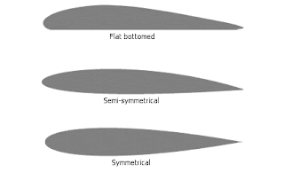
Picture an RC airplane from above, the fuselage in the middle and the wings on the right and left side. Now, look at the plane from the side, ninety degrees to the right or left from the angle you just looked at it from. What you see now is called an airfoil and they come in many shapes and sizes.
The one on the top, flat bottomed airfoils, have a lift coefficient of about 1.0 at a normal angle of attack.  The next one down, semi-symetrical airfoils, have a slightly lower lift coefficient of 0.8 to 0.9 at that same angle of attack. The bottom one, symmetrical airfoils, have a lift coefficient of 0.5 to 0.6. What's important is that higher lift coefficients decrease the stall speed of an RC plane and lower lift coefficients do the opposite to the stall speed. For example, an RC plane with a wingspan of 1 meter, weight of 986 grams and a wing area of 17.5 square decimetres with a lift coefficient of 1 will have a stall speed of 34 km/h. With a 0.8 lift coefficient, its stall speed will be 38 km/h. So, flat bottomed airfoils are generally better for lift and although symmetrical airfoils have a lower lift coefficient, they are much more suited to aerobatic planes that will need to fly inverted because there is an equal airfoil shape on both sides.  Faster RC planes often have a straight wing with no airfoil. There are lots of tables on the NACA airfoil website that will show exactly what the lift and drag coefficients are of different airfoils at different angles of attack. When the trend of lift coefficient starts decreasing rapidly, that is the point that the airfoil has stalled. Angle of attack or A.O.A is the angle of a plane's airfoil to the ground.


WINGS STALL ON THE INSIDE FIRST

Wings for full-sized airplanes are always designed so that the inside of the wing (section closest to the fuselage) stalls before the tip of the wing (section farthest from the fuselage). If not, there would be no way of controlling the roll of the plane. RC planes are sometimes designed the same way.

WASHOUT

One of the ways of making sure that the tips stall after the inner part of the wing is called washout.


One form of washout is when the tips of the wings have a lower angle of incidence or angle of attack A.O.A than the inner part of the wings closest to the fuselage.

Thursday 12 November 2015

Aspect Ratio, Wing Loading and Different Wing Shapes

As I mentioned in the previous post, the wing is the most critical part of the plane because it is what makes them fly. Different wing shapes correspond to different flight characteristics. Below are a few concepts involving wings that will definitely help with the design of an RC plane. This may be a good time to decide what flight characteristics you want your radio control model to have, or how you want it to fly e.g maneuverable, aerobatic etc. because a plane (radio control or full size) simply can't be designed for everything.


ASPECT RATIO


The aspect ratio is the length of a wing divided by it's width (chord). For example a wing that as a length of 98cm and a width of 15cm ... 98/15= . . . . . will have an aspect ratio of about 6.3. Why is this important? Here are the differences between high aspect ratio and low aspect ratio wings.


MODERATE -  HIGH ASPECT RATIO 8.0 - 15.0  (Gliders or small-midsize commercial jets)


Characteristics


  • Less induced drag due to smaller wingtips and/or winglets. I will explain drag in more detail in a later post but basically drag is one of the four forces involved with flight and it is usually air resistance hitting the plane and slowing it down while in motion. In this case, it is different. Check out this link that explains induced drag. Sorry, it is a weird video. https://www.youtube.com/watch?v=xNEx7rEv4gs. Basically, he is saying that air travelling from the high pressure zone underneath the wing to the low pressure zone on the upper surface at the very tips of the wing creates vortices which is induced drag. Winglets are basically aerodynamic fences that reduce induced drag by lowering the amount of air that travels to the upper surface. 

  •    Longer glide
  •    Looks more majestic
  •    High aspect ratio wings make RC aircraft less maneuverable 


LOW ASPECT RATIO (fighter jets, stunt planes) 


Characteristics

  • Mostly the opposite of high aspect ratio wings. Higher induced drag, lower efficiency (for an RC plane, won't glide as well), more maneuverability

The main thing to notice is that the characteristics that these airplanes needed matched the types of wings that they had. For example, 787 airliner had the high aspect ratio wing for greater efficiency and the stunt plane had the lower aspect ratio wing to be more maneuverable. The same can go for your RC plane. If you want a glider, go with a high aspect ratio wing. 


WING LOADING

Wing loading is the weight (grams) divided by the wing area (square decimetres) e.g
986 grams / 12 square decimetres = 82 grams per square decimetre of wing loading.

Higher wing loadings correspond to higher stall speeds. The stall speed is the speed that the plane no longer has enough lift to fly. The wing loading will increase if the weight is increased or the wing area is decreased and the RC plane will have to land and fly at a higher speed to avoid stalling. Reverse of this if the wing loading is decreased assuming that no changes are made to the airfoil (shape of the wing from a side view.)

If the wingspan is the usual 1 to 1.5 metres, and a weight of 1-3kg, the wing loading of an RC ducted fan jet should be around 100-130 grams per square decimetre. This will mean that stall speeds will be somewhere around 60 - 65 km/h.

A glider of the same size would have a much lower wing loading closer to 30 grams per square decimetre and may stall at 15 - 20 km/h.

A good strategy is to look at websites such as E-flite, Parkzone etc. and find a plane much like the one you are designing. Looking at some of these will be a good idea so that you know what the wing loading for your model should be.


DIFFERENT WING SHAPES

Rectangular wings: These are wings with a low-moderate aspect ratio usually. Good for carrying lots of weight because it distributes the weight of the plane equally along the wing, and a balance between efficiency (high aspect ratio) and maneuverability (low aspect ratio) . The best wing for an all-round type RC plane but has no real specialized purpose.


Swept wings: These wings are effective at high speeds, because they reduce drag allowing the plane to fly faster, however, they have less lift so they need more speed in order for an RC plane to takeoff. This is why they are the ideal wing for RC jet aircraft, due to the higher speed that they can fly at.


Delta wings: These wings take the swept wing concept even further. Delta wings have even less drag than swept wings but require even more speed to fly. That is why they were used on supersonic airliners (full size) such as the Concorde and Tu-144 but have no real use today for airliners but they do exist on some fighter jets. 


This should help you make a good start on designing the wing for your RC plane. Remember to determine the characteristics you want and then find a wing loading, aspect ratio and wing shape that will give you those characteristics.  


How Does A Wing Work?

Really, the wing is the airplane, so it is a good place to start when talking about designing an RC plane. This is also probably the most critical part of the design. First though, it is important to know how a wing actually works to generate lift.

There are several ideas out there for how a wing actually works but one of the most popular is the Bernoulli principle.


The Bernoulli principle states that air moving over the top of the wing has a further distance to travel than the air underneath. So, it must travel faster to meet the air that went underneath the wing. The faster-moving air that travels above the wing has less pressure than the slower air beneath. This creates the lifting force. 
However, the misconception with this theory was that both paths of air have to meet up together at the other side of the wing. Some experiments were done recently that suggest that the air that travels over the top of the wing actually reaches the trailing edge (back) of the wing BEFORE the air underneath. 

Another theory for lift is that when the wing is at an angle of attack (angle relative to the ground) that a plane would normally take off at,


the air hitting the underside of the wing is being directed downwards. As this happens, this air  pushes the bottom of the wing upwards in a way that creates lift at a good angle of attack. 

The bottom line is that both of these theories work for how a wing generates lift, if they are explained correctly. They are just two ways of looking at it. Personally, I agree more with the first one. I think that the second one would work more for paper planes.


Tuesday 29 September 2015

First Post on Stefan's Blog!

      Hi. My name is Stefan and I am creating this blog as part of my Communication Skills 7 class. I am very excited to start it and I will be writing about some of the experiences that I have which may involve travel and events at school.

     Some of my favourite things to do are playing with my Golden Retriever named Shadow (photos coming soon), flying RC airplanes with my Dad and music which includes cello, piano and guitar. 

     Most summers, my family goes on vacation to Europe. This year we went to France and Switzerland. The scenery, hiking and food was really amazing.

    I will be posting more soon!